I started by machining a part which contained an extension for the half-nut ways, and created a housing for the feed stop. After bolting it to the carriage, I found the ways on the carriage were machined at a slight angle. This was yet another thing that had to be improved upon, so I decided to machine it straight, and resurface the entire part while I was at it. Now everything was flat and square.


Since the disk only has to be rotated 44 degrees, this simple linkage works well. Little effort is required to move the push-rod, and the spring takes over once the disk has rotated about 20 degrees.
The rod end can be seen in this picture, along with my heavy-duty gear cover, made from .010" steel and held by 7 screws. One of the luxuries of making one's own mods is that you can overbuild things to a degree that a manufacturer could not afford to do. In this case, all materials were from my scrap bin.

I used so many screws because I am going to experiment with sealing the lid and filling the space with gear oil to see if it makes the action even smoother.
While I was improving things, I decided to fix the sloppy handwheel for moving the carriage. The shaft for the handwheel rides in a simple hole in the carriage apron, and that hole is oversized by a few thousandths. That made the handwheel very loose, and added backlash to the gear train. I fixed this by boring out the hole and pressing in a pair of ball bearings. The apron is thick enough to hold a pair of bearings, and this arrangement works very well. A single bearing would not tolerate the stresses it would be subject to.
At the same time I relocated the hole .005" closer to the other gear. This eliminated the backlash and made the handwheel feel much more precise. Now I have to relocate the rack to eliminate the considerable backlash between it and the pinion gear. Picture of apron with bearing pressed in below.

I always sweat while doing a bearing press machining job because it has to be perfect the first time. Too tight and it will not press. Too loose and it will not stay. This turned out well, and the backlash is gone. I got lucky there, for the gears are almost too tight. Initially I thought they were too tight, but they were just dirty. Cleaning them solved that, and I'm very pleased with the results.
 Filling the gearbox with oil did make it feel smoother, but once installed back on the carriage, the drag of moving the carriage dominates the feel. Then I tried running the power feed for the first time and disaster struck. The feed screw bound up, snapping the feed screw guide. I surmised that my new tight tolerance half nut was too unforgiving, causing the binding. Rather than loosen things back up, I made sure the half nut was running true by clamping it along with a a spare feed screw in my mill. Once I had the feed screw straight in the mill, I resurfaced the half-nut dovetail to eliminate any misalignment. There was a little, now there is none. I realized that the snapping of the guide was due to a combination of factors, with a primary one being the conversion to a 7x14 lathe, which is actually 6" longer than a 7x10 lathe. The feed screw is also 6" longer, and much more flexible as a result. It can easily flex itself out of engagement with the half nut teeth. The obvious solution is to add the second half nut, which balances the forces on the feed screw. However, I did not want to give up the feed screw guard so easily, for I was counting on it to shield my digital scale as well. Therefore, I made a new, and much larger feed screw guide out of steel and lined with slippery Dupont Delrin.
 The Delrin is held by five 4-40 screws, counter-bored to be flush with the steel. The guide is attached to the apron using the existing holes for the original guide, and gib retainer.
It runs very smoothly, and does a great job of keeping the feed screw clean. As large as this guide is, it will still flex when the carriage is jammed, allowing the feed screw to skip without breaking anything. Unlike the hardened steel of the original guide, the mild steel I used flexes without damage. This may prove useful as a safety feature, so I'm going to try it for a while.
The completed carriage has to be one of the more unique Mini Lathe carriages around. Built-in feed stop, oil-bath gearbox, Delrin feed screw guide, digital scales, and very tight tolerances all around.
I reassembled the lathe and my first job was parting off some sections of 1/2" steel rod. Parting steel remains a challenge, and this job was no exception. The tool seized, bringing the lathe to an abrupt stop, shattering the plastic intermediate gear in the process.

Since I had to disassemble the headstock to change the gears, I used the opportunity to change the bearings from ball to tapered rollers, also from Little Machine Shop. Ball bearings are a poor choice for a lathe spindle, but they are much cheaper for the lathe manufacturer. I had about .001" free play in my spindle with the ball bearings, and found it difficult to turn shafts precisely enough to get a consistent press fit for bearings.


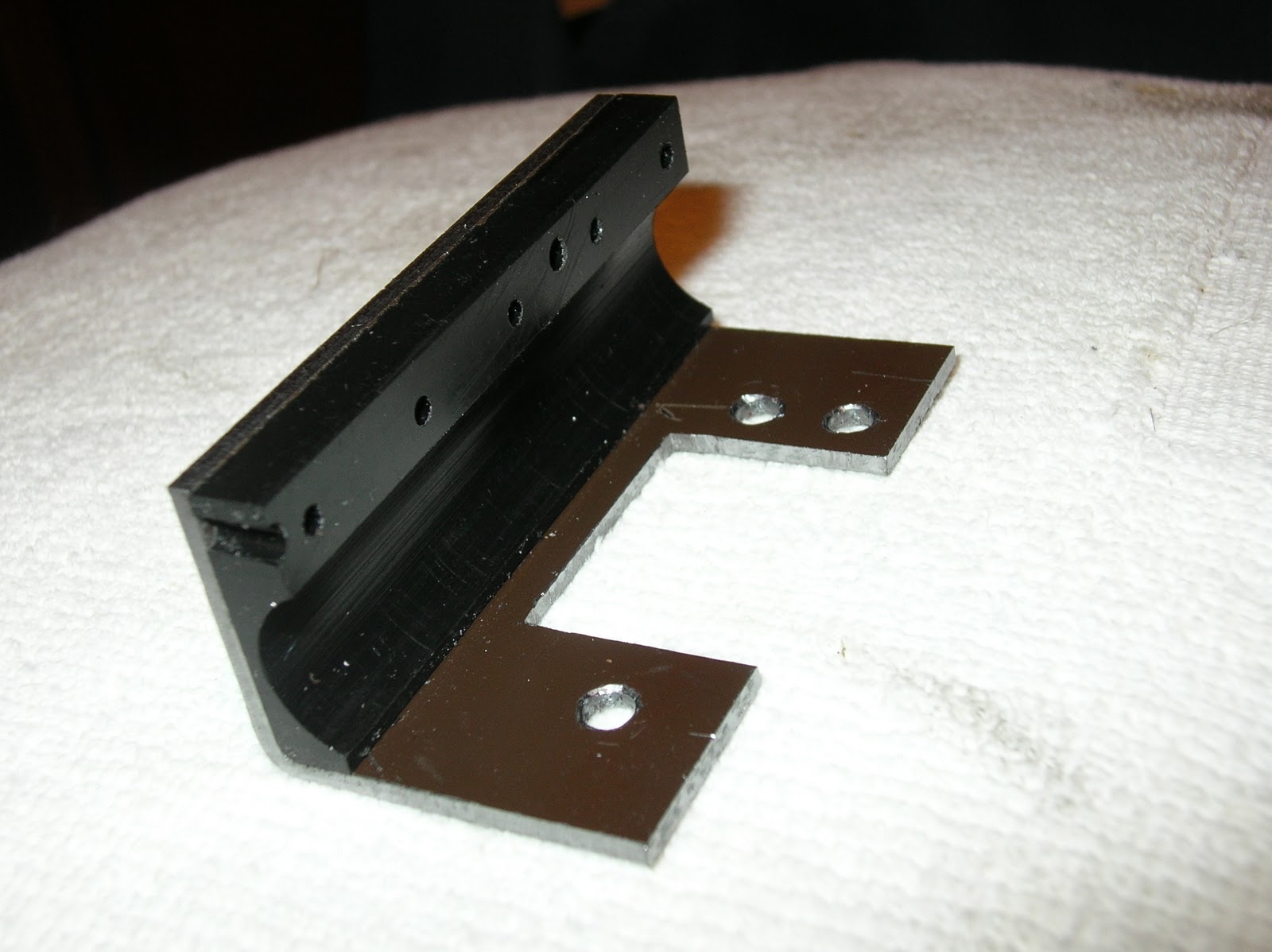
Right: Close up of the completed lathe. The carriage stop was made from a piece of steel C beam, with one leg of the C cut off and used as the clamp for the 1/4 rod which serves as the adjustable stop. The stop has a range of 2 inches, but longer rods can be substituted. The brown piece of steel primarily serves to eliminate a place where chips can accumulate. It also provides an additional attachment point for the feed screw cover.
The feed screw cover turned out well. Note how the feed screw is barely visible. The scale is also under the cover, and reasonably well protected.

 Close clearances abound. Here, the cap screws had to be recessed in counter-bores so that the scale would clear. I think they look better that way anyway.
Lots of close clearances here. The feed screw cover has just enough room to pass under the rack and pinion. The threading dial just fits above the scale.
Below: The completed lathe is a thing of precision and beauty. Smooth running, with practically indestructible steel gears and heavy-duty roller bearings. Much more accurate, thanks to the Shumatech DRO 350. The automatic feed stop works flawlessly, and the ball bearing manual feed wheel is a huge improvement. The .001" runout in the spindle is completely gone now. I used to have difficulty turning shafts to a precise diameter for more than a few centimeters before the run-out and wobble would introduce errors. As a test, I turned a 20 cm long piece of steel to 12 mm diameter over it's entire length. I had approximately 0.025 mm variation over that length. A huge improvement.
The Quick Change Tool Post seen in these pictures is a most worthy upgrade. It is a wedge type, solidly and precisely made, with all steel construction. The tools can be easily swapped and will consistently return to the same position when reinstalled. Meanwhile, the Shumatech can remember multiple tool offsets. Together, the two make a powerful combination. Tools can be swapped and new cuts made instantly with great precision.


I have noticed that many have visited here looking for ideas regarding the carriage gibs. As all Mini Lather users soon realize, the factory design is quite poor! While others have made some very elegant tapered gib designs, I chose to use the original gibs and a series of stacked shims. A lot of trial and error is required, and you will need to experiment with a variety of materials. Some of my shims are are steel, and others are thin pieces of plastic bags for fine adjustment. While it took a fair amount of time to find the best combination, the end result is very stable, and I haven't made additional adjustments in about a year.
Such a great info! its help me a lot..thanks for sharing! keep it up ya Unistrut brackets
ReplyDeleteThese are wonderful pieces of information. I have seen lathes in husband’s uncle small machine shop. I really like these lathe machines because it can turn out metal pieces into a different work of art. I understand that this lathe machine is for shaping metal, wood and other material by means of rotating metal that is also changeable, depending on what figure or shape you want it to be. It is really nice and I enjoyed watching it worked. - www.clausing-industrial.com
ReplyDeleteIf you ever have trouble with the motor controller you may want to try replacing the motor and controller with one from a treadmill. These are easy to come by and work great for small lathe or mill. I have just finished adapting a smaller older treadmill motor and controller to power a taig lathe. The controller uses a round knob for speed control and the motor is 1.25 hp treadmill rated, though probably about half that in reality but when used on the little taig it is plenty of power. I use a bike speedometer from ebay that also has a rpm readout, 12 bucks. I am in the process of doing a bench top mill treadmill motor conversion now. The DRO setup you have will be my next mod for my taig lathe, my bench top mill and my craftsman 21x30 lathe. So how do you get a treadmill motor/controller cheap? post a broken treadmill wanted ad in craigslist and people will call you up and ask you to come and haul away their old treadmill for cheap or free, I got 3 free like this in the last few months. if some one calls and wants big $$ just say no, it is not worth that much to me, then they will offer it for cheap or free to you if you only will get it out of their house!
ReplyDeleteHi, I'd like more info on the cooling fan you installed.
ReplyDeleteThanks,
Scott
Scott,
DeleteIt was something salvaged from an old computer, and it has been many years. Any small 12 volt fan will do. If you don't have a source from scrap computers, look at someplace like Mouser, Digikey or Sparkfun.
Robert
Hi Robert, I like your idea of the cooling fan. The DC power connection is OK for the FC250BJ board but won't work on previous versions and I recommend an external wall wart supply instead. I have a group of several parts changes for the FC250BJ that increases torque and improves cooling at slower machine speeds. -Pete
ReplyDelete