Way back in the late 1970's, I attended one of the premier technical schools in the country, The Williamson Free School of Mechanical Trades.
In my junior year, Omnidata, a company in the business of making sophisticated simulators to train power plant operators loaned us one for a brief period. That inspired a classmate and I to build one for our Senior Project, which is Williamson's version of a Thesis.
The microprocessor had been invented only a few years before and the first low cost computers, like the Sinclair ZX81, would arrive a few years too late. That left a technology that is under-appreciated today, analog circuitry and versatile IC's like the Operational Amplifier, or Op-Amp. These were relatively inexpensive and easy to use. A thin book covering the basic Op-Amp circuits was all we needed to get started. The Op-Amp got it's name from the fact that it does mathematical operations: Addition, Subtraction, Multiplication, Integration, and others. But these were all we needed, along with a simple digital function, known as a Comparator. This simply gave a Yes or No answer as to whether the voltage it was monitoring was above or below a certain value.

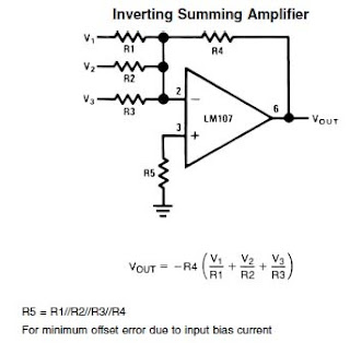
Addition: Input Voltages 1, 2, & 3 are added together. Equal resistor values gave each input equal weight, which is how we used them. A good deal of the Op-Amp's versatility came from the fact that it could accept both positive or negative voltages, which would subtract. Another way to achieve subtraction is to connect to pin 3. This is the equivalent of changing the sign of the voltage.
See the Difference Amplifier at right:
V Out is the difference between V1 and V2.
Combining elements of the summing and difference amplifiers is possible, giving one the ability to add and subtract multiple input signals.
The heart of the simulator was the Integrator circuit:
This functioned as an analog "memory" in our simulator, with the voltages stored in the capacitors representing things like the water level and steam pressure in the boiler.
A positive voltage into the "Boiler" integrator represented adding water, while a negative voltage represented water leaving as steam.
Adjusting "Water" voltage to cancel out the "Steam" voltage caused the Boiler integrator to hold a constant level.
A nearly identical circuit represented the boiler's water source, known as a Deaerator, except that the polarity was reversed. That way, the same positive voltage that "filled" the boiler, "emptied" the Deaerator. In turn, the source for the Deaerator's water, known as a "Hot Well", was also an integrator with the polarity reversed.
Put elements of the Difference Amplifier,
Summing Amplifier, and Integrator together
and you have the basic elements of a simulated feedwater circuit. Adjusting the resistor and capacitor values alters the system's response, making it possible to mimic the response of the real world system you are modeling. No, it is not sophisticated enough to respond in a non-linear fashion to simulate filling a round vessel, but it is good enough for many instructional applications.
In the real world, water level in a boiler is critical, and any power plant would be equipped with high and low alarms.
Too low a water level, and the boiler could blow up. Not a good thing. Too high a water level and the boiler will spit water out
along with the steam. A very bad thing for a modern turbine, or even an antique steam locomotive.
Therefore, we equipped our simulator with alarms, too. Here, the simple comparator circuit was ideal.
We added additional comparators to shut down the boiler in case the operator did not respond correctly to the situation.
There was also an annunciator which sounded when an alarm went off. This could be silenced by the operator pressing a Reset button, but the light for that alarm would stay lit until the condition was corrected. It sounds simple to do, but how does one allow the annunciator to sound for additional alarms? To solve this, I made a crude "One Shot" circuit consisting of a capacitor and diode. Each time an alarm sounded, a pulse of current flowed into the capacitor, just enough to latch the annunciator's relay. Every alarm needed one of these "One Shots", and there were about 20 alarms. The parts count was growing rapidly.
The boiler we were simulating had a 3 step startup sequence. First, the blowers are started to purge any fumes out of the combustion chamber. Next, the ignition pilot is lit. Finally, with the pilot burning, fuel oil is added.
Here, we used an integrator as a timer.
The integrator slowly ramped up the voltage to the 3 comparators, turning them on in the proper sequence and with the correct time delay.
The boiler was fairly sophisticated, with forced and induced draft fans, and an adjustable fuel/air ratio. The student could alter the above and get the poor combustion and furnace pressure alarms to go off, or even have the boiler shut down. Also, manually starting the boiler was possible, provided the student turned the fans on in the right sequence.
While the circuit examples I have shown appear deceptively simple, there were a lot of them, and many with customized tweaks. In addition, there were circuits to allow the Simulator to run in full automatic. The student could simply request more or less "Electricity" from the Simulator's "Generator" and watch it run itself, with feedwater pumps automatically adjusting flow and the boiler maintaining the proper steam pressure. The student could then initiate a failure, say by shutting off water to the Hot Well and then watch watch the whole thing shut down in sequence as the feedwater system went dry.
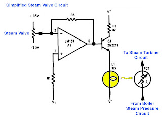
 One circuit I was especially proud of was my steam valve. This one presented a problem in that there were two variables: the amount the valve was open and the pressure of the steam. I wanted a valve with realistic operation and the tricks I used for the feedwater pumps wouldn't do. I hit upon an idea that I thought was novel, using a combination of an ordinary lightbulb and a photoresistor. It worked great. Interestingly, I found a similar circuit while looking for graphics for this blog. See the Multiplier circuit below. In their circuit, they used feedback to make the response linear. I did not need that, in fact, the non-linear response of my circuit is more realistic.
Add all of the circuits together and this is the result:
Impressive looking, isn't it? Here is the final product. Not a bad facsimile of the real thing:
There were some interesting experiences associated with building the Simulator. We had the support of our instructor, who lined up technical advisers for us. One in particular was most helpful, but somewhat skeptical, for he was in the business of building customized professional simulators that matched a customer's real equipment precisely. I'm not sure if he appreciated our simplified approach. However, while he had behind the scenes sophistication, we had great graphics and lots of blinking lights. If there is one thing that impresses non-technical types, it is lots of blinking lights. Of course, our lights were not there just to dazzle, they provided the vital alarm indications.
Our return trip with the nearly complete simulator was humorous, thanks to those blinking lights and great graphics. The humor was provided by our adviser's non-technical supervisor, who actually said to him "Why can't we make one like that?" Poor fellow. He was working with the latest in digital technology, programming in every system detail, while we had very rudimentary analog circuits lurking behind a panel with lots if blinking lights. It made us feel good, however. And, our simulator looked great, don't you agree?
Epilogue: The Simulator ran reliably for over 10 years as a teaching aid at Williamson. Then one year, some students who did not bother to read the instruction book decided the Simulator was broken, when in reality they were not following the proper start-up sequence. I made the mistake of leaving a copy of the schematic so that students interested in electronics could understand it's operation. Unfortunately, they used the schematic to try to "fix" it, and made a real mess. I took it home, and tried to sort things out. Internally, it was a rat's nest of point-to-point wiring, a giant breadboard. That was a good way for us to develop the circuits in a hurry, but having someone else go in there and cut wires made it impossible to fix. In the end, that type of simulator's days were numbered anyway. Programmable computer controls were fast replacing the traditional controls that the simulator represented. Time and technology marches on.


No comments:
Post a Comment