Sunday, February 20, 2011

More Mini Lathe Improvements

   One thing this lathe sorely needed was an automatic carriage feed stop, for forgetting to disengage the feed can lead to disaster. Disassembling the carriage for the scale project provided a great opportunity to fix this shortcoming.  I wanted a mechanism that was inside the carriage as if it was part of the machine and not added on.  As I already needed an attachment point for the scale head, I decided to incorporate both into the design.  Then I took note of the crude way the half-nut was held in place, with two screws and washers holding the gib, and holding it misaligned, making the half-nut sloppy.  Compounding this was the fact that the half-nut's dovetail protruded nearly half way out of it's ways.   Lots of things begging for improvement here!
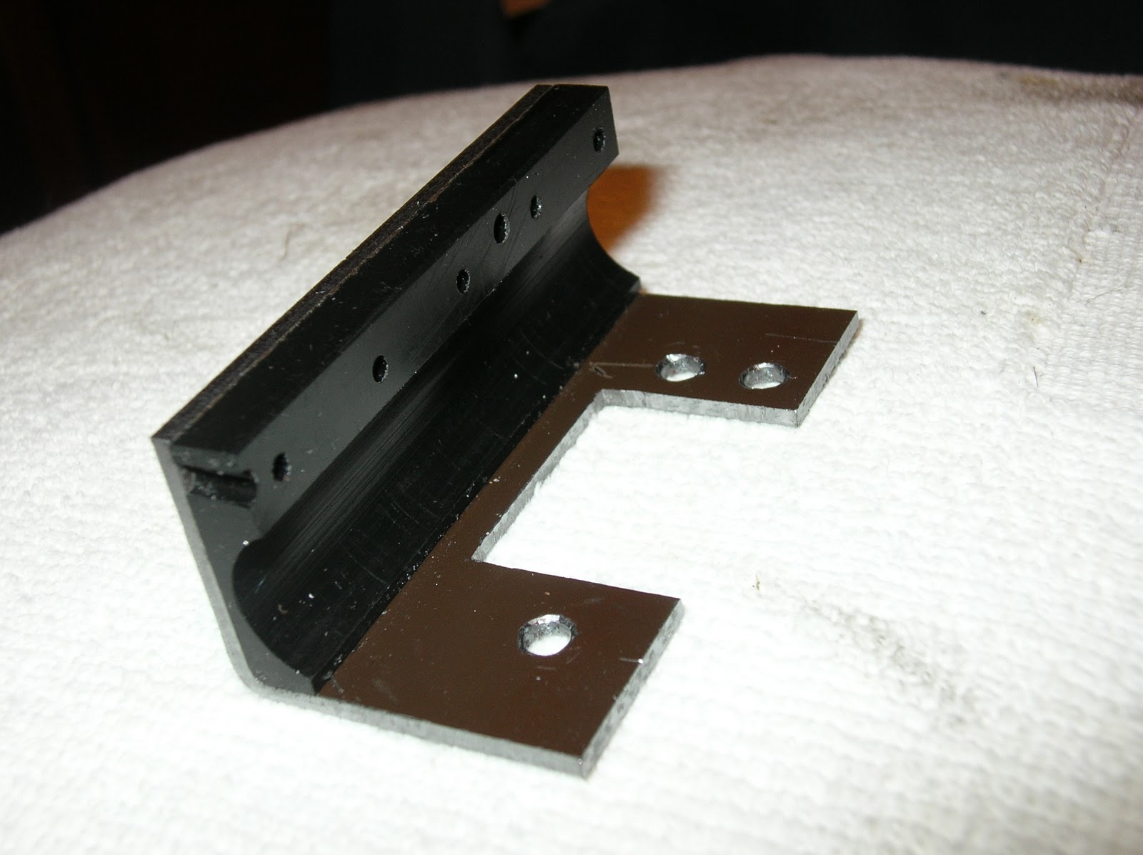
    I started by machining a part which contained an extension for the half-nut ways, and created a housing for the feed stop.  After bolting it to the carriage, I found the ways on the carriage were machined at a slight angle.  This was yet another thing that had to be improved upon, so I decided to machine it straight, and resurface the entire part while I was at it.  Now everything was flat and square.
Next step was an improved means for holding the gib.  7x10 lathes come with only the lower half-nut, instead of both upper and lower, like the 7x12 lathes.  This enabled the factory to add a shield over the top of the feed screw, something that otherwise could not be done.  I like having the shield and decided that if I could make the lower half-nut move precisely, then I would not need to add the upper.  I made a large gib retainer that fills the entire empty upper half of the ways, and provides a place for adding a spring to aid in disengaging the half-nut.  The retainer has a dovetail cut in the side opposite the screws, which holds it very securely. Combined with the extended ways, this greatly improved the precision of the half-nut.
Next step was to solve the automatic stop problem.  Moving the hand lever rotates a disc with a pair of slots in it. The half-nuts are opened and closed by pins which ride in these slots. Since the disk is inside the machine, and I wanted my mechanism inside also, I decided to directly link to the disk.  This was easy to implement by drilling a shallow hole in the disk, and making a link from a piece of 1/8" steel rod.  An illustration of how this works is shown below.
Since the disk only has to be rotated 44 degrees, this simple linkage works well.  Little effort is required to move the push-rod, and the spring takes over once the disk has rotated about 20 degrees. 
     The rod end can be seen in this picture, along with my heavy-duty gear cover, made from .010" steel and held by 7 screws.  One of the luxuries of making one's own mods is that you can overbuild things to a degree that a manufacturer could not afford to do.  In this case, all materials were from my scrap bin. 
I used so many screws because I am going to experiment with sealing the lid and filling the space with gear oil to see if it makes the action even smoother.
    While I was improving things, I decided to fix the sloppy handwheel for moving the carriage. The shaft for the handwheel rides in a simple hole in the carriage apron, and that hole is oversized by a few thousandths.  That made the handwheel very loose, and added backlash to the gear train.  I fixed this by boring out the hole and pressing in a pair of ball bearings.  The apron is thick enough to hold a pair of bearings, and this arrangement works very well.  A single bearing would not tolerate the stresses it would be subject to.
    At the same time I relocated the hole .005" closer to the other gear.  This eliminated the backlash and made the handwheel feel much more precise. Now I have to relocate the rack to eliminate the considerable backlash between it and the pinion gear. Picture of apron with bearing pressed in below.
 
I always sweat while doing a bearing press machining job because it has to be perfect the first time. Too tight and it will not press.  Too loose and it will not stay.  This turned out well, and the backlash is gone. I got lucky there, for the gears are almost too tight.  Initially I thought they were too tight, but they were just dirty. Cleaning them solved that, and I'm very pleased with the results. 
   Filling the gearbox with oil did make it feel smoother, but once installed back on the carriage, the drag of moving the carriage dominates the feel.   Then I tried running the power feed for the first time and disaster struck.  The feed screw bound up, snapping the feed screw guide.  I surmised that my new tight tolerance half nut was too unforgiving, causing the binding.  Rather than loosen things back up, I made sure the half nut was running true by clamping it  along with a a spare feed screw in my mill.  Once I had the feed screw straight in the mill, I resurfaced the half-nut dovetail to eliminate any misalignment.  There was a little, now there is none.    I realized that the snapping of the guide was due to a combination of factors, with a primary one being the conversion to a 7x14 lathe, which is actually 6" longer than a 7x10 lathe.  The feed screw is also 6" longer, and much more flexible as a result.  It can easily flex itself out of engagement with the half nut teeth. The obvious solution is to add the second half nut, which balances the forces on the feed screw.   However, I did not want to give up the feed screw guard so easily, for I was counting on it to shield my digital scale as well.  Therefore, I made a new, and much larger feed screw guide out of steel and lined with slippery Dupont Delrin. 
The Delrin is held by five 4-40 screws, counter-bored to be flush with the steel.  The guide is attached to the apron using the existing holes for the original guide, and gib retainer.
  It runs very smoothly, and does a great job of keeping the feed screw clean.   As large as this guide is, it will still flex when the carriage is jammed, allowing the feed screw to skip without breaking anything. Unlike the hardened steel of the original guide, the mild steel I used flexes without damage.  This may prove useful as a safety feature, so I'm going to try it for a while.
   The completed carriage has to be one of the more unique Mini Lathe carriages around.  Built-in feed stop, oil-bath gearbox, Delrin feed screw guide, digital scales, and very tight tolerances all around.
   I reassembled the lathe and my first job was parting off some sections of 1/2" steel rod.  Parting steel remains a challenge, and this job was no exception.  The tool seized, bringing the lathe to an abrupt stop, shattering the plastic intermediate gear in the process.  
I expected this to happen eventually, and bought steel gears from Little Machine Shop a year ago.  Actually, I'm surprised the plastic gears lasted this long, given that my modified lathe produces about 3x the torque as the original.  The large plastic spindle gear is still in great shape, but I'm changing that over to metal, too.  I've heard they are noisy, and I will report on that when I'm running again.

Since I had to disassemble the headstock to change the gears, I used the opportunity to change the bearings from ball to tapered rollers, also from Little Machine Shop.  Ball bearings are a poor choice for a lathe spindle, but they are much cheaper for the lathe manufacturer.  I had about .001" free play in my spindle with the ball bearings, and found it difficult to turn shafts precisely enough to get a consistent press fit for bearings. 

Above:  Lathe spindle with tapered roller bearings and steel gears.

Right:  Close up of the completed lathe.  The carriage stop was made from a piece of steel C beam, with one leg of the C cut off and used as the clamp for the 1/4 rod which serves as the adjustable stop.   The stop has a range of 2 inches, but longer rods can be substituted. The brown piece of steel primarily serves to  eliminate a place where chips can accumulate.   It also provides an additional attachment point for the feed screw cover.

The feed screw cover turned out well. Note how the feed screw is barely visible.  The scale is also under the cover, and reasonably well protected.

Close clearances abound.  Here, the cap screws had to be recessed in counter-bores so that the scale would clear.  I think they look better that way anyway.


Lots of close clearances here.  The feed screw cover has just enough room to pass under the rack and pinion.  The threading dial just fits above the scale.

Below:  The completed lathe is a thing of precision and beauty.  Smooth running, with practically indestructible steel gears and heavy-duty roller bearings.  Much more accurate, thanks to the Shumatech DRO 350.  The automatic feed stop works flawlessly, and the ball bearing manual feed wheel is a huge improvement. The .001" runout in the spindle is completely gone now.  I used to have difficulty turning shafts to a precise diameter for more than a few centimeters before the run-out and wobble would introduce errors.   As a test, I turned a 20 cm long piece of steel to 12 mm diameter over it's entire length.  I had approximately 0.025 mm variation over that length.  A huge improvement.
 The Quick Change Tool Post seen in these pictures is a most worthy upgrade.  It is a wedge type,  solidly and precisely made, with all steel construction.  The tools can be easily swapped and will consistently return to the same position when reinstalled.  Meanwhile, the Shumatech can remember multiple tool offsets.  Together, the two make a powerful combination. Tools can be swapped and new cuts made instantly with great precision.


   Note the grease fittings on top of the headstock.  I wanted the ability to periodically lube the steel gears without removing the headstock.  One fitting is centered over the High gear and the other over the Low gear.    I have not noted a significant increase in noise with the steel gears. However, the current draw of the motor is much higher now, as the roller bearings have much more resistance than the loose ball bearings they replaced. As I am already taxing the controller with the larger milling machine motor, I added a small computer cooling fan. 
 12 VDC is available on the board at the points where the wires are attached.  The fan was salvaged from an obsolete computer, and the shroud is made from the plastic case of a broken VCR.
The electronic control's heat sink faces down, and is at the bottom.  Exactly the opposite of what is desired, for much of the heat is trapped, and much rises up directly into the rest of the electronics.  I cut vent holes in the bottom of the case to allow cool air to be drawn in to the heat sink fins.  As the electronics are mounted on the other side, I feel the risk of metal shavings finding their way the the electronics is very low.


I have noticed that many have visited here looking for ideas regarding the carriage gibs.   As all Mini Lather users soon realize, the factory design is quite poor!  While others have made some very elegant tapered gib designs, I chose to use the original gibs and a series of stacked shims.  A lot of trial and error is required, and you will need to experiment with a variety of materials. Some of my shims are are steel, and others are thin pieces of plastic bags for fine adjustment.   While it took a fair amount of time to find the best combination, the end result is very stable, and I haven't made additional adjustments in about a year.

Wednesday, February 2, 2011

Mini Lathe Digital Readout

When my brother Stan fell ill, all my projects came to a halt.  However, Stan would not want me to stop.  While I'll never again use the lathe and mill to help him with his model railroad, there will be other projects.  Therefore I have picked up where I left off, and am in the process of adding digital readouts to my Mini Lathe.  Already heavily modified - see my Feb 18, 2010 post - the DRO will enhance it further.
Adding the scales to the lathe was more difficult than the Mini Mill because there was a lot less room to work with.  The cross-slide scale just barely fit by laying it flat on it's back.  It blocks the gib adjustment screws, but is easily removable should they need adjusting.
The compound was even more difficult, as the compound is even smaller.  I decided that I could make a housing for the scale that was larger than the compound itself, but not be in the way.  In fact, the compound scale is exactly the same length as the cross-slide scale.  Like most of my other scales, it is a cut-down Harbor Freight or similar digital caliper. The picture below shows the remains of the caliper, the cross-slide brackets, and the completed compound scale.

It extends past the compound slide in both directions, but does not interfere with the hand crank or the toolholder.  Like the cross-slide scale, it has to be removed to adjust the gibs, but removing only takes a few minutes.
Next task is adding a scale to measure carriage travel.  This will use a 12" long caliper and be mounted below the carriage, on the lathe table.
After a lot of thought about how to best add the carriage scale, I designed the mounts seen below.  They fit snugly underneath the lathe bed, and use a pair of 8-32 screws to secure them in place. After machining them, I hand-filed them in spots to make them conform to some irregular spots in the sand-cast bed.
Pictures of the brackets installed.  They fit nicely, and accurately hold the scale beam in alignment with the lathe bed.

Picture of the scale beam installed:
Next step: Make a bracket to connect the scale head to the carriage.  This led me down a different path for a while, for when I disassembled the carriage,  I saw the need for several improvements.  One of the "problems" with these lathes (and mills) is that they offer many opportunities to improve them, and turn an OK machine into a very good machine.  For example, in the above picture, the half-nut dovetail can be seen protruding far below the carriage.  I decided to fix this and make other improvements, which I will post separately.  Then I will return to the scales.  See http://robertsprojects.blogspot.com/2011/02/more-mini-lathe-improvements.html for the rest of the story

Sunday, October 24, 2010

My Brother Stan. April 16, 1955 - December 4,2010

 This is a photo of my beloved brother Stan when he worked in the library of Lebanon Valley College.  These were some of his happiest years, coming after the acceptance of the death of his first wife, Jane.  She died of lupus at 33.  However, that same disease that took her away is what first brought them together.  You see, Stan had a severe  autoimmune disease of his own, Ankylosing Spondelitis.  Like Jane, he contracted that at an early age, in his case, 14.  Their respective suffering helped form the close bond they had.   Stan had numerous operations beginning around 16, when the doctors attempted to straighten his increasingly twisted body by putting him in a body cast for many weeks.  Other operations followed, and he had to miss a year of school.  Over the years his hips, knees, elbows, wrists, ankles, and jaw were operated on.  In some cases, like his wrist, they simply eliminated the joint altogether and fused the bones. There simply wasn't enough left to work with.  The ragged bones destroyed the tendons controlling some of his fingers, so two fingers were linked to one tendon.  This of course meant that those fingers no longer moved independently.  Some of his toes' joints disintegrated to the point that the tendons began to pull the toes sideways, then towards his heel. In this case, amputation was the best remedy.  The disease caused Stan to develop a severe overbite.  This required surgery that still gives me the chills.  They cut his upper jaw out of his head, shortened it, and put it back.  Double hip replacements helped somewhat,  but there isn't much one can do with an arthritic spine except for fusing the worst vertebrae together.  While that may alleviate the pain and pressure on the spinal column, it takes away even more freedom of movement.  While the arthritis showed no signs of slowing down, Stan refused to slow down.  He had to accept the inability to play sports years ago, but giving up music was something he did not want to do.
 That meant finding an instrument that he could play given his limited movement.   The hammered dulcimer provided the perfect solution.  I built him his first one, and while it worked, it was not very good.  So, together we built a much more refined one, and he became quite good at it.
Then we rebuilt his house to make it more handicapped accessible.   The original house had a cramped bathroom with a tub that was difficult to step into. In addition, the laundry room was in the basement.  When working with the original house proved too difficult, we had the rear half of the old house completely demolished.  Then we had that replaced by a much larger wing that held a modern kitchen with laundry, and a nice master bedroom with generous closet space.  The old bedrooms were so small that we turned one into a master bath.  As a bonus, the new addition had a bright basement that was more easily accessible, for it required just a few outside steps to go down.
  This gave Stan room to practice what had become his primary hobby, model railroading.
  As nice as the house was, something important was missing.  Love and companionship.  A long standing friendship soon became something more, and he married his loving and supportive wife, Linda.   These were very good years.


Then last year Stan became ill on a trip with me to visit fellow model railroaders. In particular Wally, for whom I designed and built the table seen in my blog.  We had no idea what was wrong, but Stan soon found out.  A stage 4 malignant brain tumor.  He was told he may have as little as 6 months to live.  That was a year ago, and he is still alive thanks to some very good care, but the disease now has the upper hand.  In a tragic irony, it is the exact same thing that killed our father in 1958. Stan was 2 and I was 6 months.
  Stan did not quit.  While he was forced to give up driving, and soon after his job, he continued to build model railroad cars with meticulous detail.  Some of them won prizes in regional competitions. Some pictures of Stan and his cars are below.


Stan lived to see my birthday, which was Oct 23. We had a great time together.  It is his goal to see Christmas.  Let's pray that he makes it!

Tuesday, September 21, 2010

A home for my Mom

Late last year, my then 88 year old mom began to fail and could no longer live alone. Not a believer in warehousing the elderly, I built her a specially designed addition to my home.


The roof was the trickiest part of the design, thanks to the second floor shed dormer and the small pieces of roof on either side.  A simple shed roof would have had a very flat pitch and looked unattractive.  My solution was a hip roof.  While much more complicated to build, it allowed for an increased pitch and tied in nicely to the existing roof-line.

My very capable Amish contractor, Amos, liked my design but soon realized that some very unique trusses would have to be made for this job.


What I found interesting about this design is that none of the load is carried by the existing structure.  Instead, the trusses span 34 feet from side to side, and there is one massive truss that supports many smaller trusses at right angles.

A very strong design, but one that was difficult to insulate, thanks to the many odd spaces it created.


I spent hours cutting fiberglass to fit neatly in all of theses spaces.  It paid off, and the addition stayed comfortably cool with minimal air-conditioning this summer.


The bathroom was a real challenge.  The first floor had a powder room that could be enlarged into the addition.   I wanted a large shower and direct access to my mom's bedroom, but without using a lot of floor-space.  I also wanted a shower that one could wheel into, if handicapped.
  My solution was a shower area that was 48" x 54" and had a tile floor that drained to the center. When taking a shower, the area is closed off via a curtain that rides on hospital grade ceiling tracks. When not using the shower, the curtains are pulled back and one simply walks through to use the bathroom or exit the original door.
  An unusual design, and one that my contractor had some misgivings about, until he saw the finished product.  In the end, it works well, looks attractive, and only used 18 square feet of space in the new addition.
The tiling was a challenge, thanks to the multiple inside and outside corners, and the sloped shower floor.  But I like tiling,
and this is only the latest of several bathrooms I have done.


It is a bright and cheerful space, with plenty of room for my mom's furniture.  Far more than she could have taken with her to a retirement home.
If you noticed the missing trim above the doors, you can relax.  All of those little details are now complete.  I felt it was more important to move my mom in quickly than worry about having everything finished.


My mom and my cat in her new living room.

As my mom's health has declined, I've had to add some refinements, like a ramp to the door, and a new 4 foot wide walkway.  There were only 2 steps before, but now even a single step is a problem.

I also added a shower chair, and grab bars in the shower and on the wall opposite the toilet.  The toilet assist bars were easy to install and work well.  This should make life a lot easier for my mom.


Friday, September 17, 2010

Solar Electric Upgrade

While my 4.4kw solar electric system was performing to specifications, size does matter.  Unfortunately, my budget and choice of suitable locations were limiting factors.  As a result I had a system that could only deliver 620kwh/month when I was using 1800kwh during our hot and humid July.  My solution was to create a new mounting site over my southern facing coal bin.  In addition, I designed and machined my own mounting system.  This greatly lowered the cost, and it also gave me a system that I could not find anywhere:  One that is both roof-mounted and has adjustable tilt for summer and winter.
Fortunately for me, my PV Powered 4800 inverter had the ability to handle the 5 extra panels, bringing my cost per watt down to a very reasonable $2.50, installed.  The result was a substantial 31% increase to 5.58kw and a summer monthly output averaging 812kwh.  While still far short of July's 1800kwh, it will produce a surplus in the spring and fall, when demand drops into the 600's.
Close up of the hinged mounts.  I used the identical design for both the top and bottom rows.
However, only the top row mounts function as
hinges.  The bottom row mounts are separated at the hinge pin and a 24" piece of square tubing is
placed between the hinge halves.  Bolts are then inserted through the hinge pin holes to lock the tubing in place.
These hinges allow for 22° of movement, a few degrees less than ideal.  However, achieving more movement would have required taller hinges, which would have put more stress on this design than I desired.

Panels in the winter position.  I designed the 
coal bin roof with a 45° angle.  Not the optimum
winter angle for our latitude, but a good compromise between the requirements for the coal
bin and the solar panels.


Panels raised 22° for the summer months.  Not the optimum setting, but close enough.  Overall, I'm pleased with the design.  The tilt can be changed in a matter of minutes, and even 22 degrees gives me a significant advantage over fixed systems.


After panels are raised, a link with tapped holes
ties adjacent panels together. The bolts now serve
2 purposes, attaching the legs and linking the
panels. The result is an extremely rigid structure
that does not move even in the strongest winds.


The system has been in operation nearly one year, and has performed very well, even through our cloudy winter.  The winter output is surprisingly good, given that the system had to cope with snowstorms and fewer daylight hours. Below are charts of the electric production, my consumption, and the amount the system is saving me at our current rates of $0.15/Kwh.
Under my current agreement with my utility, excess production gets rolled over into the following month.  That reduced my November bill by $15. The May surplus was $13. That, along with the 800kwh the system made in June, reduced the bill from what would have been $161 to only $28. Since the system was installed, it has made 76% of my electricity. 
Last year, the propane hot water heater failed, and I decided it was more cost effective to use a 60 gallon electric water heater as the backup heater for the Reynolds Solar heater.  This has proven to be a good decision, for my propane use for hot water dropped to zero, while my electric bill remains low, if not zero.