Sunday, June 5, 2011

John Deere 300 Tractor - Mule Hitch Overhaul, and other repairs

About 10 years ago, I bought a 1978 John Deere 316 tractor.  In reality it is a 300 series, not to be confused with the later model 316's.  But for one year, 1978, John Deere renamed their 16 hp 300 series a 316. It is a hardworking tractor, and it shows, see below. The red seat is a boat seat.  Much cheaper than a replacement John Deere seat, and it is comfortable. It also has the virtue of having a seat-back which folds flat.  That has come in handy on numerous occasions.
 Way back in 1978, it looked like this 300:
This tractor has proven to be exceptionally reliable and rugged, and has made me into a loyal John Deere fan.  I find it remarkable that I can walk into my local dealer and they will have parts for my 33 year old tractor in stock.  Another reason I hang onto this tractor is that it has big tractor features like hydraulic fittings for accessories and individual rear brakes. The plow has both hydraulic lift and angle pistons, and they are powerful.  The plow can be lowered to the point that it lifts the front of the tractor clear off the ground. 
The angling piston is equally powerful, and I've gotten out of many a jam by using the plow's hydraulics to lift and push the tractor free.  Try doing that with the plow on a modern small tractor.
We get plenty of snow, and the little John Deere can handle most of it.  Of course there are times when it is outmatched, see below.
This is the road in front of our house. I had to give up at this point and and return home.  I was trying to reach my neighbor's house, the red one on the right. I did get my driveway clear, however.  But it was another day before I could actually go anywhere!
However, even a John Deere will show some wear after 33 years, and I recently discovered that the front support for the mower deck, called a mule hitch, was badly worn.

The mule hitch has two pulleys that turn the mower drive belt 90 degrees from vertical where it attaches to the front PTO to the horizontal pulley on the mower deck.  In spite of all this twisting and turning, the design is reliable and the current belt is now 8 years old.

  Years of vibration and the added stress of mowing rough pastures have taken their toll: The hollow pulley support shaft was nearly worn through, and the hole it rides in enlarged.


I designed repair parts that create new bearing surfaces on unworn parts of the shaft, and also solve the problem of the over-sized holes.  It is impossible to completely disassemble the mule hitch because the pulley arm was welded on after assembly.  Therefore, I had to make one of my parts with a slot instead of a hole.  It is OK however, because all of the force, and the wear, is towards the bottom of the slot.  A complicated 2 piece part is unnecessary.

I installed my parts with 1/4"-28 high strength cap screws into holes that were tapped 90% of the way through.  This made the screws extremely tight, and it is highly unlikely they will vibrate loose.
That was important for I had to mill some of the heads down for clearance.  They looks like rivets now, and are just as tight.
 Note the amount of space visible in the over-sized hole, and remember that the shaft is worn an equal amount. That added up to about 1/4" of slop, and considerable misalignment of the shaft. The other side of the hitch was worn in the opposite direction, adding to the angular misalignment of the shaft.


The reassembled hitch. One of the screw heads that was milled down is visible to the left of the pulley shaft.
   Since the outer portion of the shaft moves only when adjusting the belt, it appears that vibration, and not rotational movement, is the source of the wear. That theory is backed up by the pattern seen in the close up of the shaft.  Rotational movement would wear such a pattern smooth.  Therefore, I made my parts with a tight fit.  There is some friction, but importantly, no free play which would allow vibration to hammer the parts against each other.
 Next problem.  The hole for the spring tensioner guide rod was nearly worn through!  The original hole was at the right.  In addition, the guide rod itself was badly worn.
I realized that this wear was due to an error in the design which resulted in considerable side loads on the guide rod.  The piece of metal seen above was welded at an angle that guaranteed that the spring and rod would create excessive forces on the left side of the hole.  Compounding things was the placement of the bracket.  It is off axis from the ideal location by about 15 degrees.  While it works, and has worked for 33 years, it could be better.  Therefore I made a new spring retainer which is both better located, and better aligned to remove side forces from the guide rod.

 This strange looking part is the new spring retainer.   The force of the spring wedges it into place, and the screw is there only for insurance.


It has a pocket for the spring which holds it straight and prevents it from walking.  This, combined with the improved location reduce side forces to nearly zero.  The forces are so low that I did not replace the worn guide rod, as additional wear is unlikely.


A picture of the assembled spring tensioner.

  While the rod exits at an angle relative to the retainer, the spring pocket on the opposite side is milled at this angle, and that is what is important.
There is about 1/4" of clearance between the rod and the tractor frame, which is more than enough.
    Please note: The spring is quite powerful and under a lot of compression.  Use care when working on it!


The pulleys are once again straight, and the overhauled mule hitch should last at least as long as the original, if not longer.


    While working on the tractor, I discovered a broken motor mount. I immediately called my local John Deere dealer, and they had mounts in stock!  As I previously mentioned, great product support has made me a John Deere fan.  I expect everyday parts to be readily available, but rarely replaced parts like motor mounts?  That's impressive.


I fixed a few other things while I was at it.  The carburetor throttle shaft was also worn, and the engine would no longer idle smoothly or shut off without "dieseling".  The ball on the end of the throttle shaft was worn so much that the linkage would fall off.  Fortunately, the carburetor has a recess at the top that made it easy to press in a brass bushing, which now supports the shaft on an unworn spot. I cut off the worn ball and replaced it.   The engine now idles smoothly, and shuts down properly. If you are experiencing these problems, pay close attention to excess free play of the throttle shaft.  It does not take much!  I you can feel sideways play in your shaft, you probably have too much.  The majority of my wear was on the shaft itself, and not the holes in the carb.  It is likely that you could simply purchase a new throttle shaft from John Deere and not have to do what I did. 
    Finally, the front roller on the mower deck was
also badly worn, as was the shaft it rides on.  I made a new shaft, and epoxied brass bushings into the roller.  I also added nylon thrust washers and a spacer made from a bored out piece of 1/2" pipe to eliminate side to side play.

   The first run of the tractor after the repairs was a resounding success.  The engine starts readily, even at idle setting.  It runs smoothly, and no longer shakes excessively, thanks to the new motor mount.   The mower deck appeared to run better, easily cutting through the tall grass that had grown while I was making my repairs.   It compares favorably to much newer tractors, and is surprisingly economical.  The massive single cylinder cast iron Kohler engine burns only 3/4 of a gallon an hour while cutting grass. That is less than a gallon an acre.  It runs 6.5 hours on a full tank. Another advantage is that this tractor uses a full size car battery, not a little lawn tractor battery, which has typically lasted me maybe 3 years.  I'm still using the Pep Boys battery the previous owner installed 10 years ago!
Unfortunately for John Deere, I may be a fan, but I don't expect to be replacing my tractor anytime soon.

Update:  I removed my deck and put it away for the season.  My overhauled hitch now has two seasons of use, and while it is dirty, there is no wear on the repaired parts.  The shaft is as tight as when I made the repair.


 If you install a plow with a hydraulic angle piston, that piston is connected to the same hydraulic lines as the deck lift piston.  For the angle piston to work properly, the deck piston has to be immobilized.  I have seen this done by putting a manual valve on the inlet line to the lift piston.  When using the plow, the operator reaches under the tractor and closes the valve. I find this to be an overly complicated fix to a simple problem.  Here is my solution.  I took a piece of steel and drilled two holes in it 14 1/2 inches apart.  One hole is 1/2 inch and the other is 3/8 inch.   Put the half inch hole in the mower deck attach point, and use a 3/8 inch bolt to attach the steel bar to the 3/8 inch hole in the deck lift shaft.  Your deck height knob must be screwed all the way down, as seen here.
The piston now cannot move more than 1/8 of an inch.  Much easier and cheaper than the hydraulic valve idea.

Here are links to my Kohler K341 engine overhaul and my Mower Deck Rebuild.

I have now added a Harbor Freight winch to the rear of the tractor.  You can read about that here.


Sunday, March 20, 2011

Mini Mill Upgrade. Adding a Larger Table

I just added an enlarged table to my Mini Mill, bought from Little Machine Shop (where else?).  When I acquired my Mini Mill, I soon discovered one of it's major shortcomings.  The small table had too much flexibility in the Y direction.  I found this to be more of a problem than the often mentioned column flexibility.  To give you an idea just how much larger this table, here are the two side by side.

Among other improvements, the feed screw is supported at both ends, while the old table's screw is only supported at the handwheel end.  In the upper left of the picture is the new table's end cap with brass bushing.  Perhaps most important, the saddle is much wider and has 4 gib adjusting screws, instead of only 2.  I believe that contributed to the lack of stiffness in the old design.
The whole assembly weighs 20 pounds more than the original, and it is noticeable.  The "mini" mill no longer feels so mini anymore.  It is far stiffer, and the 20 TPI feed screw feels more precise than the old 16 TPI one.  I highly recommend this mod, and if you are considering buying a mini mill, I would not buy one without this table.  The LMS High Torque Mill comes with this table and a powerful new motor.
Below.  My upgraded mill. The 4 inch vise no longer looks out of proportion, as it did on the smaller table.
Swapping the scales to the new table was a breeze, thanks to T nut slot on the front face.  The front T slot is much smaller than the standard sized slots on the table, so I made my own T nuts, with 8-32 threaded holes.   While the scales may appear to be inadequately protected,  they have held up well, and have performed flawlessly for over a year to date.
      All mini mill tables lack a decent thrust bearing on the Y axis, and the axis on my original table seized up one day.  I fixed that by adding a bronze bushing where the spalling took place.  I had to use a bushing, for there is not enough room there for a bearing.  I machined a recess in the shaft retainer for the bushing. It is a big improvement, but only works in the direction of the table traveling away from the operator.  
     Thrust loads in the other direction are carried by the handwheel, where it contacts the shaft retainer.  Again, it is simply steel rubbing against steel.  Here there is room for a real thrust bearing, and Enco sells some inexpensive, and very thin bearings.  The one I used is a 1/2" ID (12.7mm) bearing, but that is not critical, for the shaft retainer handles the radial load.  What is important is that the recess in the retainer is accurately aligned, for that is what keeps the bearing in alignment.


  Here is where a 4 jaw independent chuck and dial indicator are essential. Do not trust the outside diameter.  I found my shaft hole was slightly off center relative to the OD of the retainer.

  I am very pleased with the results.  I can now set the thrust bearing at zero clearance, which was not possible before.  That removed some of the backlash in the Y direction.  When moving the table towards the operator, it is nearly effortless, thanks to the roller bearing. More effort is required to move the table when the bronze bushing is taking the load, but it is a great improvement over the original setup.
Here is my solution to the lock nut problem. Rather than replace the lock nut pair with a nylon insert nut, I made a small wrench that fits inside the handwheel. This wrench wedges itself inside the handwheel, making it possible to tighten the outer nut without the inner nut moving.  It is very effective and never loosens.


      Here is something that was not possible with the original table:  A 4 inch vise, and a 4 inch rotary table with 5 inch chuck mounted on the table at the same time.
       I  moved my trusty Shumatech 350 to the lathe and installed a 550 on the mill.  The 550 remembers 10 workspaces, which means I can store separate zero values for the vise and rotary table.

Sunday, February 20, 2011

More Mini Lathe Improvements

   One thing this lathe sorely needed was an automatic carriage feed stop, for forgetting to disengage the feed can lead to disaster. Disassembling the carriage for the scale project provided a great opportunity to fix this shortcoming.  I wanted a mechanism that was inside the carriage as if it was part of the machine and not added on.  As I already needed an attachment point for the scale head, I decided to incorporate both into the design.  Then I took note of the crude way the half-nut was held in place, with two screws and washers holding the gib, and holding it misaligned, making the half-nut sloppy.  Compounding this was the fact that the half-nut's dovetail protruded nearly half way out of it's ways.   Lots of things begging for improvement here!
    I started by machining a part which contained an extension for the half-nut ways, and created a housing for the feed stop.  After bolting it to the carriage, I found the ways on the carriage were machined at a slight angle.  This was yet another thing that had to be improved upon, so I decided to machine it straight, and resurface the entire part while I was at it.  Now everything was flat and square.
Next step was an improved means for holding the gib.  7x10 lathes come with only the lower half-nut, instead of both upper and lower, like the 7x12 lathes.  This enabled the factory to add a shield over the top of the feed screw, something that otherwise could not be done.  I like having the shield and decided that if I could make the lower half-nut move precisely, then I would not need to add the upper.  I made a large gib retainer that fills the entire empty upper half of the ways, and provides a place for adding a spring to aid in disengaging the half-nut.  The retainer has a dovetail cut in the side opposite the screws, which holds it very securely. Combined with the extended ways, this greatly improved the precision of the half-nut.
Next step was to solve the automatic stop problem.  Moving the hand lever rotates a disc with a pair of slots in it. The half-nuts are opened and closed by pins which ride in these slots. Since the disk is inside the machine, and I wanted my mechanism inside also, I decided to directly link to the disk.  This was easy to implement by drilling a shallow hole in the disk, and making a link from a piece of 1/8" steel rod.  An illustration of how this works is shown below.
Since the disk only has to be rotated 44 degrees, this simple linkage works well.  Little effort is required to move the push-rod, and the spring takes over once the disk has rotated about 20 degrees. 
     The rod end can be seen in this picture, along with my heavy-duty gear cover, made from .010" steel and held by 7 screws.  One of the luxuries of making one's own mods is that you can overbuild things to a degree that a manufacturer could not afford to do.  In this case, all materials were from my scrap bin. 
I used so many screws because I am going to experiment with sealing the lid and filling the space with gear oil to see if it makes the action even smoother.
    While I was improving things, I decided to fix the sloppy handwheel for moving the carriage. The shaft for the handwheel rides in a simple hole in the carriage apron, and that hole is oversized by a few thousandths.  That made the handwheel very loose, and added backlash to the gear train.  I fixed this by boring out the hole and pressing in a pair of ball bearings.  The apron is thick enough to hold a pair of bearings, and this arrangement works very well.  A single bearing would not tolerate the stresses it would be subject to.
    At the same time I relocated the hole .005" closer to the other gear.  This eliminated the backlash and made the handwheel feel much more precise. Now I have to relocate the rack to eliminate the considerable backlash between it and the pinion gear. Picture of apron with bearing pressed in below.
 
I always sweat while doing a bearing press machining job because it has to be perfect the first time. Too tight and it will not press.  Too loose and it will not stay.  This turned out well, and the backlash is gone. I got lucky there, for the gears are almost too tight.  Initially I thought they were too tight, but they were just dirty. Cleaning them solved that, and I'm very pleased with the results. 
   Filling the gearbox with oil did make it feel smoother, but once installed back on the carriage, the drag of moving the carriage dominates the feel.   Then I tried running the power feed for the first time and disaster struck.  The feed screw bound up, snapping the feed screw guide.  I surmised that my new tight tolerance half nut was too unforgiving, causing the binding.  Rather than loosen things back up, I made sure the half nut was running true by clamping it  along with a a spare feed screw in my mill.  Once I had the feed screw straight in the mill, I resurfaced the half-nut dovetail to eliminate any misalignment.  There was a little, now there is none.    I realized that the snapping of the guide was due to a combination of factors, with a primary one being the conversion to a 7x14 lathe, which is actually 6" longer than a 7x10 lathe.  The feed screw is also 6" longer, and much more flexible as a result.  It can easily flex itself out of engagement with the half nut teeth. The obvious solution is to add the second half nut, which balances the forces on the feed screw.   However, I did not want to give up the feed screw guard so easily, for I was counting on it to shield my digital scale as well.  Therefore, I made a new, and much larger feed screw guide out of steel and lined with slippery Dupont Delrin. 
The Delrin is held by five 4-40 screws, counter-bored to be flush with the steel.  The guide is attached to the apron using the existing holes for the original guide, and gib retainer.
  It runs very smoothly, and does a great job of keeping the feed screw clean.   As large as this guide is, it will still flex when the carriage is jammed, allowing the feed screw to skip without breaking anything. Unlike the hardened steel of the original guide, the mild steel I used flexes without damage.  This may prove useful as a safety feature, so I'm going to try it for a while.
   The completed carriage has to be one of the more unique Mini Lathe carriages around.  Built-in feed stop, oil-bath gearbox, Delrin feed screw guide, digital scales, and very tight tolerances all around.
   I reassembled the lathe and my first job was parting off some sections of 1/2" steel rod.  Parting steel remains a challenge, and this job was no exception.  The tool seized, bringing the lathe to an abrupt stop, shattering the plastic intermediate gear in the process.  
I expected this to happen eventually, and bought steel gears from Little Machine Shop a year ago.  Actually, I'm surprised the plastic gears lasted this long, given that my modified lathe produces about 3x the torque as the original.  The large plastic spindle gear is still in great shape, but I'm changing that over to metal, too.  I've heard they are noisy, and I will report on that when I'm running again.

Since I had to disassemble the headstock to change the gears, I used the opportunity to change the bearings from ball to tapered rollers, also from Little Machine Shop.  Ball bearings are a poor choice for a lathe spindle, but they are much cheaper for the lathe manufacturer.  I had about .001" free play in my spindle with the ball bearings, and found it difficult to turn shafts precisely enough to get a consistent press fit for bearings. 

Above:  Lathe spindle with tapered roller bearings and steel gears.

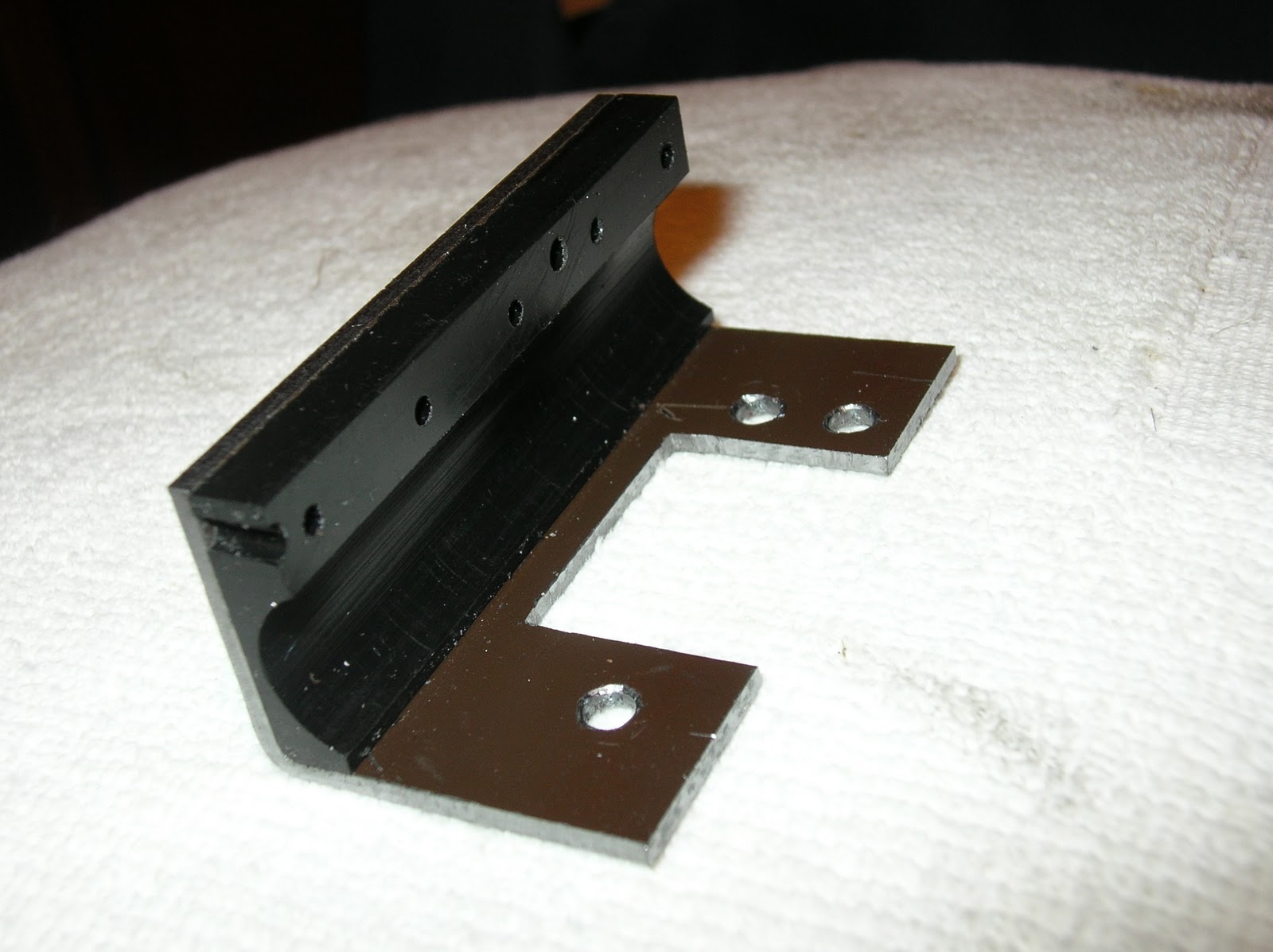
Right:  Close up of the completed lathe.  The carriage stop was made from a piece of steel C beam, with one leg of the C cut off and used as the clamp for the 1/4 rod which serves as the adjustable stop.   The stop has a range of 2 inches, but longer rods can be substituted. The brown piece of steel primarily serves to  eliminate a place where chips can accumulate.   It also provides an additional attachment point for the feed screw cover.

The feed screw cover turned out well. Note how the feed screw is barely visible.  The scale is also under the cover, and reasonably well protected.

Close clearances abound.  Here, the cap screws had to be recessed in counter-bores so that the scale would clear.  I think they look better that way anyway.


Lots of close clearances here.  The feed screw cover has just enough room to pass under the rack and pinion.  The threading dial just fits above the scale.

Below:  The completed lathe is a thing of precision and beauty.  Smooth running, with practically indestructible steel gears and heavy-duty roller bearings.  Much more accurate, thanks to the Shumatech DRO 350.  The automatic feed stop works flawlessly, and the ball bearing manual feed wheel is a huge improvement. The .001" runout in the spindle is completely gone now.  I used to have difficulty turning shafts to a precise diameter for more than a few centimeters before the run-out and wobble would introduce errors.   As a test, I turned a 20 cm long piece of steel to 12 mm diameter over it's entire length.  I had approximately 0.025 mm variation over that length.  A huge improvement.
 The Quick Change Tool Post seen in these pictures is a most worthy upgrade.  It is a wedge type,  solidly and precisely made, with all steel construction.  The tools can be easily swapped and will consistently return to the same position when reinstalled.  Meanwhile, the Shumatech can remember multiple tool offsets.  Together, the two make a powerful combination. Tools can be swapped and new cuts made instantly with great precision.


   Note the grease fittings on top of the headstock.  I wanted the ability to periodically lube the steel gears without removing the headstock.  One fitting is centered over the High gear and the other over the Low gear.    I have not noted a significant increase in noise with the steel gears. However, the current draw of the motor is much higher now, as the roller bearings have much more resistance than the loose ball bearings they replaced. As I am already taxing the controller with the larger milling machine motor, I added a small computer cooling fan. 
 12 VDC is available on the board at the points where the wires are attached.  The fan was salvaged from an obsolete computer, and the shroud is made from the plastic case of a broken VCR.
The electronic control's heat sink faces down, and is at the bottom.  Exactly the opposite of what is desired, for much of the heat is trapped, and much rises up directly into the rest of the electronics.  I cut vent holes in the bottom of the case to allow cool air to be drawn in to the heat sink fins.  As the electronics are mounted on the other side, I feel the risk of metal shavings finding their way the the electronics is very low.


I have noticed that many have visited here looking for ideas regarding the carriage gibs.   As all Mini Lather users soon realize, the factory design is quite poor!  While others have made some very elegant tapered gib designs, I chose to use the original gibs and a series of stacked shims.  A lot of trial and error is required, and you will need to experiment with a variety of materials. Some of my shims are are steel, and others are thin pieces of plastic bags for fine adjustment.   While it took a fair amount of time to find the best combination, the end result is very stable, and I haven't made additional adjustments in about a year.

Wednesday, February 2, 2011

Mini Lathe Digital Readout

When my brother Stan fell ill, all my projects came to a halt.  However, Stan would not want me to stop.  While I'll never again use the lathe and mill to help him with his model railroad, there will be other projects.  Therefore I have picked up where I left off, and am in the process of adding digital readouts to my Mini Lathe.  Already heavily modified - see my Feb 18, 2010 post - the DRO will enhance it further.
Adding the scales to the lathe was more difficult than the Mini Mill because there was a lot less room to work with.  The cross-slide scale just barely fit by laying it flat on it's back.  It blocks the gib adjustment screws, but is easily removable should they need adjusting.
The compound was even more difficult, as the compound is even smaller.  I decided that I could make a housing for the scale that was larger than the compound itself, but not be in the way.  In fact, the compound scale is exactly the same length as the cross-slide scale.  Like most of my other scales, it is a cut-down Harbor Freight or similar digital caliper. The picture below shows the remains of the caliper, the cross-slide brackets, and the completed compound scale.

It extends past the compound slide in both directions, but does not interfere with the hand crank or the toolholder.  Like the cross-slide scale, it has to be removed to adjust the gibs, but removing only takes a few minutes.
Next task is adding a scale to measure carriage travel.  This will use a 12" long caliper and be mounted below the carriage, on the lathe table.
After a lot of thought about how to best add the carriage scale, I designed the mounts seen below.  They fit snugly underneath the lathe bed, and use a pair of 8-32 screws to secure them in place. After machining them, I hand-filed them in spots to make them conform to some irregular spots in the sand-cast bed.
Pictures of the brackets installed.  They fit nicely, and accurately hold the scale beam in alignment with the lathe bed.

Picture of the scale beam installed:
Next step: Make a bracket to connect the scale head to the carriage.  This led me down a different path for a while, for when I disassembled the carriage,  I saw the need for several improvements.  One of the "problems" with these lathes (and mills) is that they offer many opportunities to improve them, and turn an OK machine into a very good machine.  For example, in the above picture, the half-nut dovetail can be seen protruding far below the carriage.  I decided to fix this and make other improvements, which I will post separately.  Then I will return to the scales.  See http://robertsprojects.blogspot.com/2011/02/more-mini-lathe-improvements.html for the rest of the story